

-
About RychenFocus on high-tech research and development, energy-saving product design and production in the fields of fluid transportation (water pump, fan), fine control combustion, high-efficiency heat exchange and high-efficiency permanent magnet motor, and provide professional technical transformation services to provide users with professional comprehensive energy-saving solutions.

-
SolutionFocus on high-tech research and development, energy-saving product design and production in the fields of fluid transportation (water pump, fan), fine control combustion, high-efficiency heat exchange and high-efficiency permanent magnet motor, and provide professional technical transformation services to provide users with professional comprehensive energy-saving solutions.
-
ProductsFocus on high-tech research and development, energy-saving product design and production in the fields of fluid transportation (water pump, fan), fine control combustion, high-efficiency heat exchange and high-efficiency permanent magnet motor, and provide professional technical transformation services to provide users with professional comprehensive energy-saving solutions.
-
BlogWe focus on high-tech research and development, energy-saving product design and production in the fields of fluid transportation (water pump, fan), fine control combustion, high-efficiency heat exchange and high-efficiency permanent magnet motor, and provide professional technical transformation services to provide users with professional comprehensive energy-saving solutions.
High temperature thermal protection technology
Release time:
2022-02-21
In 1996, the U.S. government formulated the ARRMD and Hyper-X Program [89-94], focusing on the development of hypersonic aircraft, with X-43 types of verification aircraft, including X-43A,X-43B,X-43C and X-43D models. Among them, the X-43A flight speed is up to 9.8Ma, and its main structure is steel beam, steel and aluminum alloy skin and rear partition. The rear partition plate is made of titanium alloy to meet the thermal protection performance requirements.
In 1996, the United States Government established the ARRMD and Hyper-X Program[89-94], Focus on the research and development of hypersonic aircraft, the verification aircraft type is X-43, including X-43A,X-43B,X-43C and X-43D models. Among them, the X-43A flight speed is up to 9.8Ma, and its main structure is steel beam, steel and aluminum alloy skin and rear partition. The rear partition plate is made of titanium alloy to meet the thermal protection performance requirements. The upper and lower surfaces of the aircraft are thermally protected by 1.3cm alumina reinforced thermal barrier ceramics, and the outer surfaces contain fiber toughening coatings. The leading edge part of the wing with high heat flux is made of C/C composite material, and the surface is covered with a layer of SiC material. The fuselage leading edge adopts the passive thermal protection scheme. The surface is wrapped with a layer of C/C composite material, which can withstand up to 1649 ℃, and the surface is covered with a layer of SiC coating. Figure 36 is a schematic diagram of a X-43 high speed aircraft.
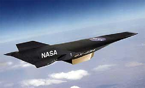
Figure 36 Schematic Diagram of X-43 High Speed Vehicle
In 1999, NASA began to X-37 the project. The X-37B testing machine developed by Boeing Company can fly at a speed of 20Ma and spend 270 days in orbit. The model adopts a monolithic toughened and antioxidant composite structure (TUFROC), the maximum withstand temperature can reach 1700 ℃, and the density is only 1/4 of the reinforced C/C[95-98], Figure 37 is a X-37B diagram.
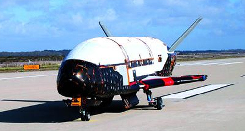
Fig. 37 X-37B diagram
In 2011, the US Navy, Boeing and Hewlett-Packard co-developed the Hypersonic Flight Technology Demonstration Program (HYFLY)"[99, 100]. The flight speed of the program verifier can reach up to 6.5Ma, and titanium alloy is used as a whole. From 2005 to 2008, four flight tests were carried out successively, all of which failed. 38 is a schematic diagram of a HYFLY validator.
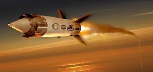
Fig. 38 Schematic diagram of HYFLY verification machine
In 2003, the United States began the FALON program.[101-104]The goal is to develop aircraft with speeds up to 20 times the speed of sound. Among them, the goal of the verification model X-51A plan is to develop an aircraft with a Ma of 5~7 that can strike the world within 1 hour. Two tests in 2009 and 2011 failed, and the third test in 2012 reached a speed of 5 times the speed of sound and flew about 230 nautical miles. Figure 39 is a X-51A schematic diagram.
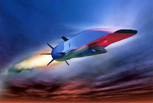
Fig. 39 Schematic Diagram of X-51A
Russia is also making great efforts to develop hypersonic vehicle technology. In 1991, it implemented the "cold" plan to verify that the model SA-5 the "Ganmeng" missile with a maximum flight speed of 6.5 times the speed of sound. Figure 40 is the layout structure diagram of the verification model. In addition, Russia has also developed the "Rainbow-D2" and "Eagle -31" verification aircraft, which can reach a maximum flight speed of 6.5Ma and 5.5Ma. The above-mentioned planned aircraft technology is at the world's advanced level.[105, 106].
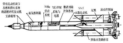
Figure 40 Structure of SA-5 Gammon Missile
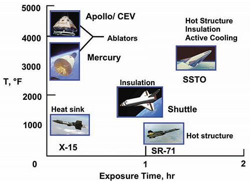
Figure 41 Thermal management methods for different temperature ranges and operating times
Different thermal management strategies should be employed for different types of aircraft, Figure 41 is an aircraft classified for temperature and time. For example, the heat sink method is X-15 because the aircraft has a short flight time and a moderate temperature. The SR71 uses a high-temperature structural design due to its longer flight time and moderate temperature.
Figure 42 shows the temperature distribution of the surface of the space shuttle. The traditional aluminum skin structure is used. Due to repeated use at 350 °F, the heat protection tile is used as the heat insulation material on the windward side and the heat insulation blanket is used on the leeward side. The leading edge of the aircraft is made of carbon material.
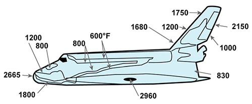
Fig. 42 Space Shuttle Surface Temperature Distribution
References:
[89] W.R.P. Michael E W, Affordable Hypersonic Missiles for Long -Range Precision Strike, Johns Hopkins APL Technical Digest, 20 (1999) 415.
[90] K.R. R, Hypersonic Missile Propulsion System, Pratt and Wtney Wst Plm Bach Fl, 1998.
[91] P.P. Peter W M K, Affordability Analysis for DARPA Programs, Johns Hopkins APL Technical Digest, 21 (2000) 439.
[92] R.V.L. McClinton C R, Preliminary X -43 Flight Test Results, Acta Astronautica, 57 (2005) 266-276.
[93] F.P.P. Lamorte N, Dalle D J, Uncertainty Propagation in Integrated Airframe Propulsion System Analysis for Hypersonic Vehicles, Journal of Propulsion and Power, 31 (2014) 54-68.
[94] Guo Chaobang, Li Wenjie, Hypersonic Vehicle Structural Materials and Thermal Protection System, Flying Missile, (2010) 88-94.
[95] F. X, Background of X-37B Space Vehicle Development, Spacecraft Environment Engineering, 27 (2010) 558-565.
[96] Lu Qin, Jiang Guiqing, Luo Xiaoguang, Hu Longfei, New Technology of Light Non-Ablative Thermal Protection for X-37B Space Vehicle, Modern Defense Technology, 40 (2012) 16-20.
[97] G.A. C, Orbital Test Vehicle and Derivatives, AIAA Space 2011 Conference & Exposition, 2011.
[98] W. Huang, S. Li, J. Liu, Z. Wang, Investigation on high angle of attack characteristics of hypersonic space vehicle, Science China-Technological Sciences, 55 (2012) 1437-1442.
[99] H.D.P. Brase L O, Flutter and Divergence Assessment of the HyFly Missile, AIAA Paper, (2009).
[100] H.-S. Kim, K.-S. Kim, S.-J. Oh, J.-Y. Choi, W.-S. Yang, A Preliminary Design of Flight Test Conditions for a Sub-scale RBCC Engine using a Sounding Rocket, International Journal of Aeronautical and Space Sciences, 16 (2015) 529-536.
[101] M.J.S. Hank J M, Mutzman R C, The X-51A Scramjet Engine Flight Demonstration Program, AIAA Paper, (2008).
[102] J.T.R. Spravka J J, Current Hypersonic and Space Vehicle Flight Test and Instrumentation, AIAA Paper, 2015.
[103] S.A. Bulman M J, Combined Cycle Propulsion: Aerojet Innovations for Practical Hypersonic Vehicles, AIAA Paper, (2011).
[104] C. H, USAF Successfully Tests X-51A WaveRider, Jane's Defence Weekly, 47 (2010) 130-139.
[105] Cai Guobiao, Xu Dajun, Hypersonic Vehicle Technology, Science Press, Beijing, 2012.
Contact Us
11/F, Building 1, Guozheng Center, 497 Zhengli Road, Yangpu District, Shanghai
Follow us